|
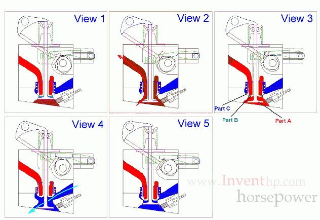
Operation of Uniport Valve

The following few paragraphs will explain how the Uniport Valve works
with the help of the above views. Some of the arrows on these views
show the direction of the exhaust and intake flow and they are marked
on the view which represents the time frame for which the event occurs.
The following paragraph will describe the parts while the paragraph
after that is a view by view description of how these parts work
together.
Part A looks much
like a standard poppet valve used in most engines. Part B is similar in
shape except its stem is bigger around and the head is smaller. There
is a hole bored through its stem so that the stem of part A may pass
through it as shown. Part C is shaped similar to a hollow
cylinder which is free to move in a bore concentric with the other two
moving parts. Note part C has two different seats ground on its end.
The inner seat is made to seat with part B and the outer one is made to
seat with the end of the intake runner. Part A is basically a typical
poppet valve and it closes against the cylinder head in typical fashion
closing off all flow.
View
1 shows the position of the three moving parts just before the exhaust
cycle begins. From there parts A and B move to the position you see in
View 2, allowing exhaust gas to pass through part C and out through the
exhaust passage. In View 3 you will see that part B has returned to a
position which will stop all exhaust flow. As part B continues in the
same direction, it moves part C so that the intake cycle can begin. The
two continue to a point shown in View 4, which would be about halfway
through the intake cycle. At the end of the intake cycle part A would
have closed as shown on View 5 where it would stay during the
compression and work cycles. During that time part B and C have roughly
250 degrees of crank angle to get to the position that was in shown
in View 1. Of course this completes a full cycle for a
four-cycle
engine.
|